How Does an Induction Heating Coil Work? A Guide to Coil Design
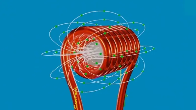
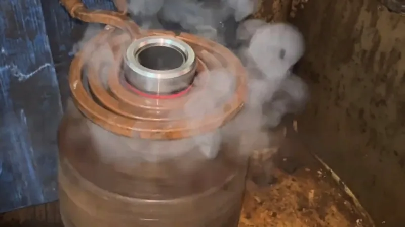
When a steel shaft needs to be heated quickly before hardening, or a metal part needs to be heated in one specific area without affecting the rest of the workpiece, induction heating can do this without direct contact. An alternating current is passed through a coil to create a changing magnetic field, which induces eddy currents in the conductive workpiece and generates heat.
The workpiece heats up rapidly as the induced eddy currents generate heat within the material, allowing its temperature to rise quickly and locally,which can change its hardness, microstructure, strength, or formability.
1. What Is Induction Heating?
Induction heating is a non-contact heating process that uses an alternating electromagnetic field to heat electrically conductive materials.
An alternating current passes through an induction coil, generating a changing magnetic field around the coil. When a conductive workpiece is placed inside or near this magnetic field, electrical currents are induced within the workpiece. These currents are commonly called eddy currents.
Because the workpiece has electrical resistance, the induced currents generate heat as they flow through the material. The workpiece can therefore be heated without direct contact with a flame, heating element, or other heat source.
2. How Does an Induction Heating Coil Work?
The basic process can be simplified as:
Alternating current → magnetic field → induced eddy currents → electrical resistance → heat
The induction coil is not normally the part that heats the workpiece directly. Instead, it generates the alternating magnetic field that transfers electromagnetic energy to the workpiece.
Copper is commonly used for the induction coil because it has very high electrical conductivity. However, the copper conductor also generates heat when carrying a high current. For this reason, induction heating coils are commonly made from water-cooled copper tubing, with cooling water flowing continuously through the internal passage of the tube.
Key Factors Affecting Induction Heating Coil Performance
3, Frequency and Skin Effect
Induction heating equipment can operate at different frequencies depending on the workpiece, required heating depth, heating speed, power level, and application.
| Item | High-Frequency Induction Heating | Medium-Frequency Induction Heating |
|---|---|---|
| Main characteristic | Faster and more concentrated heating, particularly near the surface | Greater heating penetration, suitable for deeper heating |
| Common workpieces | Small shafts, gears, bolts, tools, and thin-wall components | Steel bars, round stock, shafts, gears, and larger forgings |
| Common applications | Hardening, surface treatment, brazing, and localized heating | Overall heating, forging, heat treatment, and other deeper-heating applications |
Skin Effect in Induction Heating
The skin effect causes induced current to concentrate near the surface of a conductive workpiece when it is exposed to an alternating magnetic field. As frequency increases, the current tends to penetrate less deeply into the material, making higher frequencies more suitable for surface or shallow heating. Lower frequencies generally allow deeper current penetration and are more suitable for heating a larger volume of the workpiece.
Copper Tubes Shapes and Cross-sections
The copper tube is one of the key components of a water-cooled induction heating coil. It must carry high electrical current while allowing cooling water to circulate through the coil.
Both high-frequency and medium-frequency induction heating equipment can use water-cooled copper tubing to form induction coils. Round, square, rectangular, and specially shaped copper tubes may be selected depending on the coil design, electrical load, cooling requirements, available space, and workpiece geometry.
The choice of copper tube cross-section is not determined by frequency alone. Electrical current, cooling capacity, mechanical requirements, bending conditions, and the available space inside the equipment can all affect the required tube dimensions and shape.
Round copper tube
Round copper tube is one of the most common choices for water-cooled induction coils. Its continuous circular passage provides a practical path for cooling water, and the tube can be bent into various coil configurations.
Square copper tube
Square copper tubing can be used when a different conductor geometry or a more compact coil arrangement is required. Its flat sides can provide closer contact between adjacent sections of the coil or between the coil and a designed heating area.
Rectangular copper tube
Rectangular copper tubing provides flexibility in designing the conductor cross-section. Depending on the orientation of the tube, the wider face can be positioned toward the workpiece or used to achieve a specific coil configuration.
Special-shaped copper tube
Custom copper tube profiles may be developed for specialized induction coils where standard round, square, or rectangular tubing cannot provide the required conductor geometry, cooling passage, or installation space.
The copper tube dimensions are also important. Outside dimensions and wall thickness influence current-carrying capacity, mechanical strength, bending performance, and the internal passage available for cooling water.
Induction Coil Shapes and Geometry
The copper tube is usually bent or formed into a coil designed around the workpiece and the area that needs to be heated.
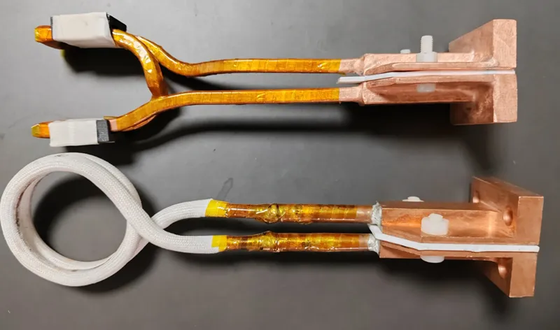
Common induction coil configurations include:
Helical coil
Spiral coil
Pancake coil
Ring coil
Hairpin coil
Custom-shaped coil
A cylindrical workpiece such as a round bar or shaft may use a helical coil surrounding its outer surface. Flat components may use pancake or flat coil configurations, while gears, tubes, shafts, and irregularly shaped components may require specially designed coils.
The shape of the induction coil itself is usually designed around the shape of the workpiece, the required heating zone, and the heating process.
This means that the copper tube used to make an induction coil does not have to remain in its original straight-tube geometry. It may be bent, formed, and arranged into a specific three-dimensional shape to create the required electromagnetic field around the workpiece.
Distance Between the Coil and Workpiece
The gap between the induction coil and workpiece affects electromagnetic coupling and heating efficiency. A smaller gap generally provides stronger coupling and faster, more efficient heating, while a larger gap reduces coupling and requires more power to achieve the same heating effect. The gap should therefore be kept as small as practical while allowing sufficient clearance for safe operation and cooling.
4. How to design an Induction Heating Coil?
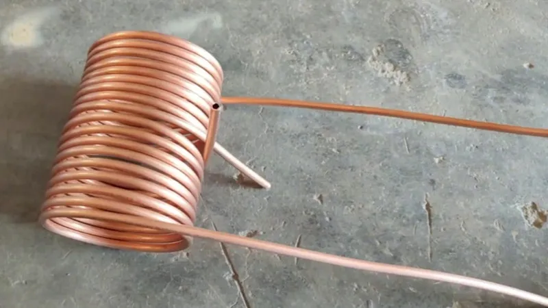
Building an induction heating coil starts with the workpiece dimensions and the required heating conditions. The coil diameter, number of turns, tube cross-section, spacing between turns, and distance between the coil and workpiece all affect the electrical and thermal performance of the system.
Coil Diameter
The coil diameter is generally related to the size and shape of the workpiece. For a cylindrical workpiece, the coil needs to be large enough to surround the workpiece while maintaining an appropriate coil-to-workpiece clearance.
A larger workpiece will generally require a larger coil, but coil diameter should not be considered independently from the other electrical parameters.
Number of Turns
The number of turns is another important design parameter.
It is tempting to assume that a larger coil diameter always requires fewer turns, but this is not necessarily true. The required number of turns depends on the overall electrical design, including operating frequency, power supply, required inductance, workpiece dimensions, heating zone, and coil geometry.
Therefore:
Coil diameter and number of turns cannot be determined independently.
The coil designer normally considers these parameters together to achieve the required heating performance.
Tube Size and Wall Thickness
The copper tube must also have sufficient cross-sectional area to carry the required current and sufficient wall thickness to provide mechanical integrity during bending and operation.
At the same time, the tube needs an adequate internal passage for cooling water.
This creates a balance between:
Electrical current capacity
Copper cross-sectional area
Cooling-water flow
Tube dimensions
Coil geometry
Bending requirements
For this reason, copper tube selection is an important part of induction coil construction.
Bending and Forming
The copper tube must be capable of being bent into the required coil geometry without excessive flattening, cracking, or deformation of the internal water passage.
For complex coils, the dimensional accuracy of the formed copper tube can be just as important as the original straight-tube dimensions.
Why is copper used for induction heating coils?
Copper has high electrical conductivity, which helps carry the high current needed to generate the alternating magnetic field. It also has good thermal conductivity and can be formed into different coil shapes, making it well suited for water-cooled induction coils. Its relatively low electrical resistance helps reduce power losses in the coil, while its excellent heat transfer capability allows heat generated during operation to be removed efficiently by cooling water. These properties help maintain stable coil performance during repeated heating cycles.
5. How to Select Copper Tubes for Induction Heating Coils?
Selecting copper tubing for an induction heating coil involves more than choosing a tube that fits the coil dimensions.
The tube needs to meet the electrical, thermal, mechanical, dimensional, and forming requirements of the heating system.
Copper Grade
High-conductivity copper is commonly selected for induction heating coils.
Typical copper grades may include:
C11000 / Cu-ETP / T2
C10200 / Cu-OF / TU1
Oxygen-Free Copper (OFC)
The specific copper grade depends on the required electrical conductivity, purity, manufacturing requirements, and application.
For high-current induction coils, electrical conductivity is particularly important because lower electrical resistance helps reduce power losses in the coil.
Tube Cross-Section
Round, square, rectangular, and custom-shaped copper tubes can all be considered for induction coil applications.
A round tube is widely used because it combines good cooling-water flow with relatively straightforward bending and forming.
Square or rectangular tubing may be selected when the coil requires a particular conductor geometry or a more compact arrangement.
For specialized heating systems, custom-shaped copper profiles may be designed to fit the required coil geometry.
Outside Dimensions and Wall Thickness
The outside dimensions and wall thickness of the copper tube affect several aspects of coil performance.
They influence:
Current-carrying capacity
Mechanical strength
Bending performance
Cooling-water passage
Coil dimensions
Available space between the coil and workpiece
The appropriate tube size therefore depends on the complete coil design rather than frequency alone.
Cooling Requirements
Cooling is one of the main reasons hollow copper tubing is used for induction coils.
During operation, the coil carries a high electrical current and develops its own heat losses. Cooling water flowing through the internal passage removes this heat and helps maintain the coil at an acceptable operating temperature.
Depending on the system, important tube and cooling considerations may include:
Internal diameter
Wall thickness
Water-flow capacity
Pressure resistance
Internal cleanliness
Connection method
The internal water passage should remain sufficiently open after bending and forming so that cooling water can flow through the complete coil.
Bending and Formability
Induction coils often require copper tubing to be bent into relatively tight or complex shapes.
The tube therefore needs suitable mechanical properties and dimensional consistency for bending and forming.
Excessive deformation during bending can reduce the internal water passage and affect cooling performance. Cracking or surface damage can also shorten the service life of the coil.
For custom induction coils, the copper tube may therefore need to be supplied according to specific outside dimensions, wall thickness, temper, length, and forming requirements.
Frequently Asked Questions
1. How hot can induction heating get?
Induction heating can heat many metals to several hundred or even over 1,000°C, depending on the material, heating power, frequency, workpiece size, and heating time. Steel and other ferrous metals can be heated to forging or melting temperatures with suitable induction heating equipment.
2. How do you maintain the copper tube in an induction coil?
Regularly check the cooling-water flow, water quality, tube surface, connections, and bends. Keep the cooling passage clean and make sure there is no blockage, leakage, cracking, or excessive deformation of the copper tube. Proper cooling is essential for extending coil life.
3. Why do induction heating coils use hollow copper tubes?
Hollow copper tubes allow cooling water to flow through the coil while the copper carries the electrical current. This removes heat generated in the coil during operation and helps prevent excessive temperature rise.
4. How long does an induction heating coil last?
The service life varies widely depending on heating power, operating frequency, duty cycle, cooling conditions, coil design, and mechanical stress. A properly designed and maintained water-cooled copper coil can be used for a long period, while overheating, poor cooling, and repeated mechanical deformation can significantly shorten its life.
5. What causes an induction heating coil to overheat?
Common causes include insufficient cooling-water flow, blocked water passages, excessive electrical current, poor coil design, damaged or deformed copper tubing, and unsuitable operating conditions. Regularly checking the cooling system and copper tube condition can help prevent overheating.
Conclusion
Copper tubing plays an important role in induction heating because it combines high electrical conductivity with the ability to provide internal water cooling.
Both high-frequency and medium-frequency induction heating equipment can use copper tubing to form water-cooled induction coils. Round, square, rectangular, and specially shaped copper tubes can be used depending on the electrical, cooling, mechanical, and dimensional requirements of the coil.
The final coil may take the form of a helical, spiral, pancake, ring, hairpin, or custom-shaped coil according to the geometry of the workpiece and the required heating area.
For copper tube selection, frequency should be considered together with current, power, workpiece dimensions, heating depth, coil geometry, cooling requirements, and forming conditions. This is why induction heating applications may require copper tubing in different grades, cross-sections, wall thicknesses, and customized dimensions.