Aluminum Extrusions for Energy Storage Battery Trays and Liquid Cooling Plates
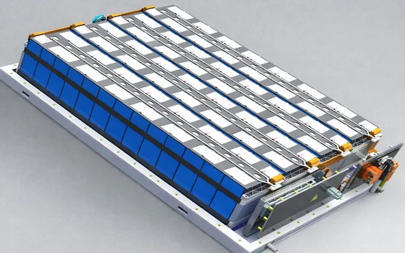
As energy storage systems become larger and more power-dense, battery thermal management is becoming increasingly important. During charging and discharging, battery cells generate heat that must be transferred away efficiently to maintain temperature uniformity, operating efficiency, and long-term reliability.
Liquid cooling is widely used when passive cooling is no longer sufficient. Within a liquid-cooled battery system, the cooling plate provides the thermal interface between the battery module and the coolant circuit. It must transfer heat efficiently while also providing sufficient mechanical support and maintaining reliable coolant flow without leakage.
For this type of application, aluminum extrusion offers an important manufacturing advantage. Instead of machining a complex cooling structure from a solid aluminum block, an extrusion die can create a wide, flat profile with continuous internal cavities or channels along its entire length. The extruded profile can then be cut and CNC machined to create coolant ports, mounting holes, threads, sealing surfaces, and other precision features.
This article focuses on extruded aluminum liquid cooling plates used in energy storage battery systems, with particular attention to 6061 and 6063 aluminum alloys, profile design, extrusion manufacturing, CNC machining, and the function of different structural features.
1.What Does an Extruded Aluminum Liquid Cooling Plate Look Like?
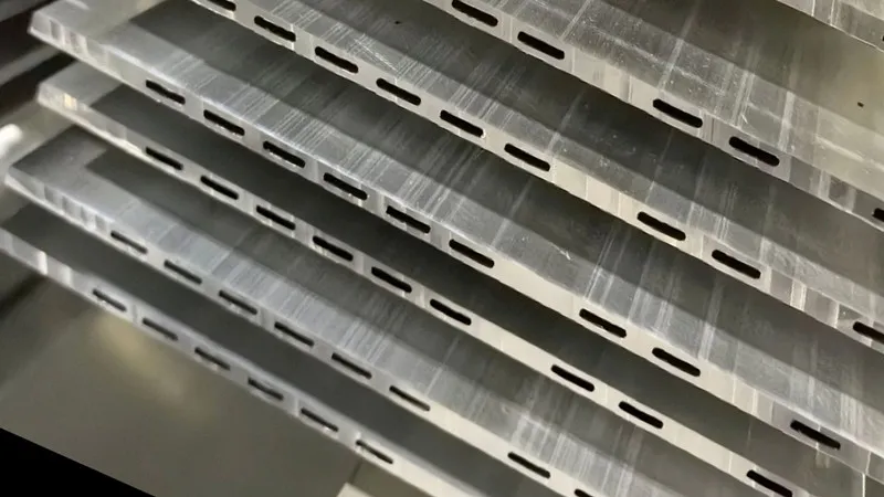
An extruded battery cooling plate can look quite different from a conventional flat aluminum plate. The cross-section is usually engineered specifically for the required combination of heat transfer, coolant flow, structural stiffness, weight, and manufacturability.
A typical wide extruded cooling profile may include several distinct features:
A wide and relatively flat central surface
Continuous hollow chambers along the length of the profile
Internal walls or ribs separating the chambers
Thin or moderately thick profile walls
External mounting or joining features
Machined coolant inlet and outlet interfaces after extrusion
The profile is produced continuously through an extrusion die, so these geometric features extend along the extrusion direction.
1.1 Wide and Flat Overall Profile
The broad, flat geometry provides a large surface area for contact with the battery module or thermal interface material.
The cooling plate may be installed beneath or adjacent to battery cells or modules. Depending on the battery pack architecture, heat generated by the cells passes through a thermal interface material and into the aluminum cooling structure.
A larger effective contact area can help distribute heat across the cooling plate rather than concentrating it in a small region.
The wide, low-profile design is also useful where vertical installation space is limited. Instead of using a tall cooling structure, engineers can distribute the cooling area horizontally.
1.2 The Wide Central Surface
The central flat area is more than a simple supporting surface. It can function as the primary heat-transfer interface between the battery and the cooling structure.
A simplified heat-transfer path is:
Battery Cell → Thermal Interface Material → Aluminum Cooling Plate → Coolant → Heat Exchanger
For this reason, the dimensions and surface condition of the battery-contact area can be important. Depending on the application, requirements may include control of:
Flatness
Surface roughness
Thickness
Dimensional tolerance
Surface cleanliness
The exact requirements depend on how the cooling plate is integrated into the battery system.
1.3 Continuous Hollow Chambers
One of the most distinctive features of an extruded cooling profile is its continuous hollow structure.
The internal chambers extend along the extrusion direction and can be designed to serve different purposes. Depending on the specific cross-section, some chambers may function as coolant passages, while others may primarily reduce weight or increase structural stiffness.
This is an important advantage of extrusion.
The hollow geometry is not simply a way to remove unnecessary material. It can combine several functions within one aluminum profile:
Create space for coolant flow
Reduce overall weight
Increase cross-sectional stiffness
Control material distribution
Reduce the amount of material that would otherwise need to be removed by machining
The exact function of each cavity depends on the cooling plate design.
1.4 Internal Walls and Ribs
Internal walls separate different chambers and contribute to the rigidity of the profile.
From a structural perspective, the location and thickness of these walls influence the stiffness of the extruded section.
From a thermal-management perspective, the walls may also form the boundaries of coolant passages and therefore participate in heat transfer between the aluminum and the coolant.
This means that the internal geometry must balance several requirements at the same time.
A wall that is too thick can add unnecessary weight and material cost. A wall that is too thin may create challenges in extrusion, dimensional stability, machining, or mechanical performance.
1.5 Multiple Extrusions Can Form a Larger Cooling Structure
A single extruded profile does not necessarily represent the entire finished cooling plate.
Depending on the battery system architecture, several extruded profiles can be arranged, joined, or integrated into a larger cooling structure.
This modular approach allows manufacturers to produce long, repeatable profiles first and then cut them to the required dimensions.
The result can be a large cooling surface suitable for battery modules or energy storage battery packs without requiring the entire structure to be machined from a single large aluminum block.
2. Why Is Extrusion Suitable for Battery Liquid Cooling Plates?
The main advantage of extrusion is not simply that aluminum is lightweight. The more important advantage is that a complex and continuous cross-section can be produced directly through a die.
For battery cooling applications, this can provide several manufacturing and engineering benefits.
2.1 Complex Cross-Sections Can Be Produced in One Extrusion
An extrusion die can form multiple geometric features simultaneously.
Depending on the design, a single profile may include:
Flat surfaces
Hollow chambers
Cooling passages
Internal ribs
Grooves
Mounting features
Reinforcing sections
This reduces the need to manufacture every feature separately.
Instead of starting with a solid aluminum plate and removing a large amount of material to create internal cavities, extrusion creates much of the required geometry during the forming process itself.
2.2 Continuous Cooling Geometry
Extrusion is particularly suitable for structures in which the cross-section remains constant along the length.
A cooling channel that runs continuously through the profile can be formed directly during extrusion.
This is useful for long battery cooling components because the same cross-sectional geometry can be produced repeatedly over a long length and then cut into individual sections.
2.3 Better Material Utilization
Machining a complex hollow structure from a solid aluminum block can generate significant amounts of chips and scrap.
With extrusion, much of the final geometry is created before CNC machining begins.
The machining process can therefore focus on features that require precision rather than removing large volumes of material.
This can improve material utilization and reduce machining time, particularly for high-volume production.
2.4 Structural Stiffness Without Excessive Weight
A well-designed hollow profile can provide a favorable relationship between weight and stiffness.
Internal walls, ribs, and distributed material can increase the section's resistance to bending and deformation without making the entire component solid.
For a battery cooling plate, this can be valuable because the component may need to perform two roles simultaneously:
Thermal function + Structural function
The cooling plate needs to transfer heat, but it may also support or locate battery modules and withstand mechanical loads from assembly, transportation, and operation.
3. How Is an Extruded Aluminum Cooling Plate Manufactured?
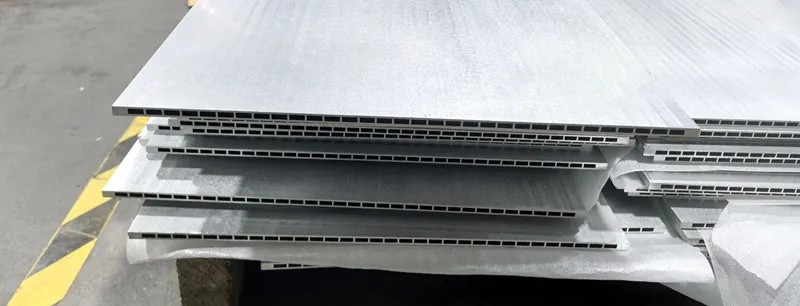
The manufacturing process can generally be understood as:
Aluminum Billet → Extrusion → Cooling and Straightening → Cutting → CNC Machining → Assembly → Inspection and Leak Testing
The exact process depends on the final cooling plate design.
3.1 Aluminum Billet Selection
The process starts with an aluminum extrusion billet.
For this type of application, 6061 and 6063 are two relevant alloy choices.
The alloy, temper, billet quality, and required profile geometry should be considered together rather than selecting an alloy based on strength alone.
The extrusion billet must be suitable for producing the required hollow or multi-chamber profile while meeting the final mechanical and dimensional requirements.
3.2 Extrusion Die Design
The extrusion die is one of the most important parts of the manufacturing process.
The basic cross-section of the finished profile is determined by the die opening.
For a liquid cooling profile, the die may be designed to create:
Outer dimensions
Internal chambers
Channel walls
Ribs
Flat battery-contact surfaces
Mounting features
Other continuous profile geometry
The die design must also consider wall thickness distribution and metal flow during extrusion.
A highly asymmetric or complex profile can be more challenging to extrude because the aluminum must flow through different sections of the die at controlled rates.
For hollow profiles, the die structure must also create the internal geometry while maintaining sufficient dimensional stability during production.
3.3 Heating and Extrusion
The aluminum billet is heated to an appropriate processing temperature and placed into the extrusion press.
A ram then pushes the billet through the die.
As the aluminum passes through the die opening, it takes the shape of the designed cross-section and emerges as a continuous profile.
This is fundamentally different from CNC machining.
CNC machining removes material to create a shape.
Extrusion forms the required cross-section directly.
That distinction is one of the main reasons extrusion is attractive for long, complex cooling structures.
3.4 Cooling, Stretching, and Straightening
After leaving the extrusion die, the profile is cooled under controlled conditions.
Depending on the alloy and required temper, subsequent processing may include:
Cooling or quenching
Stretching
Straightening
Heat treatment or aging
These operations help establish the required mechanical properties and dimensional condition of the profile.
For cooling plates, dimensional stability is important because subsequent CNC machining and assembly depend on the profile maintaining its intended geometry.
3.5 Cutting to Length
The continuous extrusion is then cut into individual sections according to the required cooling plate dimensions.
Precision sawing may be used to achieve consistent lengths and suitable end conditions for subsequent machining.
At this stage, the profile has its basic cooling-plate geometry, but it is not necessarily a finished liquid cooling component.
4. Why Are 6061 and 6063 Suitable for This Type of Extruded Structure?
4.1 6063: Excellent Extrudability for Complex Profiles
6063 aluminum is particularly well suited to complex extrusion profiles because of its excellent extrudability. It can be used to produce long sections with multiple cavities, relatively thin walls, and detailed cross-sectional features. 6063 aluminum extrusion is therefore a practical option when profile complexity and extrusion performance are important considerations.
4.2 6061: Strength and Machinability
6061 offers higher strength than 6063 in commonly supplied tempers while also providing good machinability. This makes it attractive when an extruded cooling component must provide both thermal-management functions and structural support. 6061 aluminum bar stock and extrusions can also be used for related machined components where strength and dimensional control are important.
4.3 The Profile Design Should Drive the Alloy Selection
There is no universal rule that 6061 or 6063 is always better for an extruded liquid cooling plate.
The decision should consider:
Cross-sectional complexity
Wall thickness
Required mechanical strength
Cooling-channel geometry
CNC machining requirements
Dimensional tolerances
Production volume
Surface requirements
Final assembly method
For a highly complex hollow extrusion where extrusion performance is the dominant consideration, 6063 may be advantageous.
For a structurally demanding cooling component requiring significant CNC machining, 6061 may be preferable.
The final alloy should therefore be selected together with the extrusion die and the complete manufacturing process.
5. What Happens After Extrusion? CNC Machining of the Cooling Plate
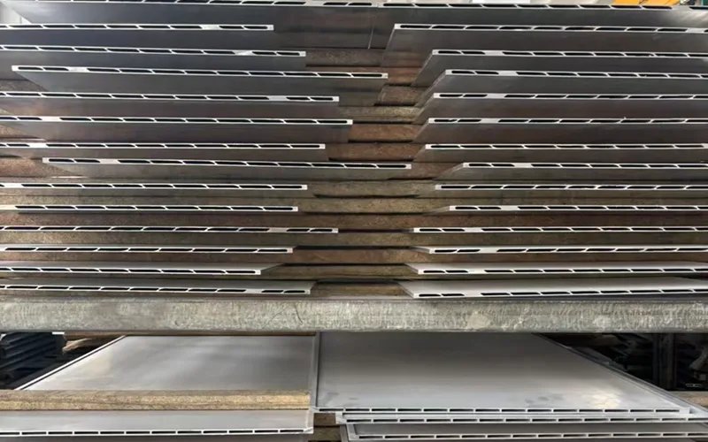
Extrusion creates the basic continuous geometry, but it cannot economically produce every feature required by the finished cooling component.
This is where secondary machining becomes important.
A typical process may include:
Extrusion → Cutting → CNC Machining → Cleaning → Assembly → Leak Testing
5.1 Precision Cutting
The long extruded profile is cut into individual cooling plate sections.
The cut length needs to match the battery system dimensions and may also need to account for subsequent machining and assembly requirements.
5.2 CNC Drilling
Drilled holes can be added for:
Mounting
Fasteners
Brackets
Assembly interfaces
Drainage or other functional requirements
The location of these holes can be critical when the cooling plate must align with battery modules or the surrounding enclosure.
5.3 CNC Milling
Milling can create features that cannot be formed economically during extrusion, such as:
Slots
Pockets
Recesses
Flat surfaces
End features
Mounting interfaces
CNC machining therefore complements rather than replaces extrusion.
5.4 Machining Coolant Inlets and Outlets
The coolant inlet and outlet are among the most important post-extrusion features.
The extrusion may provide the basic internal cooling passage, while CNC machining creates the external connection interface.
Depending on the system, this may include:
Circular ports
Threaded ports
Connector interfaces
Manifold interfaces
End openings
The port geometry must match the coolant circuit and the selected fittings.
5.5 Thread Machining
Threaded holes may be machined to accept fittings or other components.
Thread dimensions and machining tolerances need to match the final connection system.
5.6 Sealing Surfaces and Grooves
Liquid cooling systems require reliable sealing.
Depending on the design, the cooling plate may use:
O-rings
Gaskets
Sealing compounds
Welded or mechanically joined interfaces
CNC machining may therefore be used to produce accurate sealing surfaces or grooves.
This is one area where machining accuracy can directly affect the reliability of the final cooling system.
5.7 Mounting Holes and Slots
The finished cooling plate may also require mounting features to connect it to:
Battery modules
Battery trays
Frames
Enclosures
Supporting structures
These features are typically added during secondary machining.
6. Why Combine Aluminum Extrusion with CNC Machining?
The combination of extrusion and CNC machining is particularly effective because the two processes perform different jobs.
Extrusion is used for:
Continuous hollow geometry
Cooling channels
Long profile sections
Internal cavities
Ribs
Basic structural geometry
CNC machining is used for:
Precision holes
Ports
Threads
Grooves
End faces
Sealing surfaces
Mounting interfaces
In simple terms:
Extrusion creates the geometry; CNC machining creates the precision features.
This approach can be significantly more efficient than machining the entire cooling plate from solid aluminum.
For example, if a long cooling plate were manufactured entirely from a solid aluminum block, a large amount of material would need to be removed to create internal cavities. With extrusion, the cavities and major profile geometry are formed directly during the extrusion process.
CNC machining can then be reserved for the areas where tight dimensional control or customized interfaces are actually required.
For smaller machined fittings, connectors, or related components, solid 6061 aluminum bar can also be used when an extruded hollow profile is not appropriate.
7. How Does the Extruded Cooling Plate Work in an Energy Storage Battery System?
The cooling plate is normally integrated into the battery thermal management system rather than functioning as an independent component.
Depending on the battery architecture, an extruded liquid cooling plate may be positioned beneath or adjacent to battery cells or modules.
A simplified heat-transfer path is:
Battery Cell / Module
↓
Thermal Interface Material
↓
Aluminum Cooling Plate
↓
Coolant Channels
↓
Coolant
↓
Heat Exchanger
During battery operation, heat generated inside the cells is transferred toward the cooling structure.
The aluminum plate spreads this heat across its surface and transfers it toward the coolant passages. Coolant flowing through the internal channels then carries the heat away to the rest of the thermal management system.
In this configuration, the aluminum extrusion can perform multiple functions simultaneously:
Heat spreading
Heat transfer
Structural support
Coolant channel formation
Weight reduction
This multifunctional role is one of the main reasons extruded aluminum profiles are attractive for energy storage battery cooling structures.
8. What Does Each Structural Feature Contribute to the Cooling Plate?
The cross-section of an extruded cooling plate should not be viewed simply as a shape. Each part of the profile can serve a specific engineering purpose.
| Structural Feature | Main Function |
|---|---|
| Wide flat surface | Battery contact and heat transfer |
| Hollow chambers | Coolant passages and/or weight reduction |
| Internal walls | Separate channels and increase structural stiffness |
| Ribs | Improve rigidity with controlled material usage |
| Thin profile walls | Reduce weight and material consumption |
| Multiple cooling channels | Support coolant distribution and heat removal |
| Machined ports | Connect the cooling plate to the coolant circuit |
| Machined sealing surfaces | Help prevent coolant leakage |
| Mounting holes and slots | Secure the cooling plate within the battery system |
The actual function of each feature depends on the specific extrusion design.
For example, not every hollow chamber must be a coolant passage. Some may exist primarily to reduce weight or improve the stiffness-to-weight ratio of the profile.
This is why cooling-plate design should be considered as a combination of thermal, hydraulic, structural, and manufacturing requirements rather than simply a matter of creating internal holes in an aluminum profile.
9. Key Design Considerations for Extruded Liquid Cooling Plates
Designing an extruded cooling plate requires balancing several competing requirements.
9.1 Wall Thickness
Wall thickness affects:
Extrudability
Mechanical strength
Weight
Material consumption
Thermal resistance
Dimensional stability
An excessively thin wall may make extrusion and dimensional control more challenging.
An excessively thick wall can increase weight and material consumption without necessarily providing proportional benefits.
The appropriate wall thickness therefore depends on the alloy, profile geometry, extrusion capability, pressure requirements, and structural loads.
9.2 Cooling Channel Geometry
The internal channel geometry affects both thermal and hydraulic performance.
Important considerations can include:
Channel size
Number of channels
Flow path
Coolant distribution
Pressure drop
Heat-transfer area
A cooling channel should not simply be made as large as possible.
A larger channel may reduce flow resistance, but the final design also needs to provide effective contact between the coolant and the heat-transfer surfaces.
The cooling system therefore needs to balance heat-transfer requirements with hydraulic performance.
9.3 Flatness of the Battery-Contact Surface
The surface facing the battery or thermal interface material can be particularly important.
Poor flatness can create uneven contact conditions and potentially increase thermal resistance in certain areas.
For this reason, the final cooling plate may require controlled flatness or additional machining depending on the application.
9.4 Dimensional Tolerance
Two different tolerance systems should be considered:
Extrusion tolerances
These control the basic profile dimensions produced by the die.
CNC machining tolerances
These control precision features such as:
Holes
Ports
Threads
Grooves
Sealing surfaces
The two processes work together, but they do not provide identical levels of dimensional control.
9.5 Leakage Prevention
Because the cooling plate carries liquid coolant, leakage resistance is a fundamental requirement.
Potential leakage points include:
Coolant ports
Threaded connections
End closures
Sealing grooves
Joined sections
Welded areas, where applicable
The final design and manufacturing process should therefore include appropriate sealing and leak-testing procedures.
10. Extruded Cooling Plate vs. Machined Solid Aluminum Plate
For long and continuously shaped cooling components, extrusion can offer significant manufacturing advantages compared with machining the entire structure from solid material.
Extruded + CNC Machined
Complex cross-section is formed directly
Internal cavities require less material removal
Good material utilization
Efficient for long profiles
CNC is focused on precision features
Suitable for repeated production
Machined from Solid Aluminum
Very flexible for prototypes
No extrusion die is required
Suitable for highly customized geometries
Can involve substantial material removal
Can require longer machining time for large hollow structures
This does not mean extrusion is always the better choice.
For prototypes, very small quantities, or geometries that change frequently, machining from solid material can sometimes be more practical.
For repeated long profiles with a stable cross-section, however, extrusion can provide a more efficient manufacturing route.
11. Where Are These Cooling Plates Used in Energy Storage Systems?
Extruded liquid cooling plates can be incorporated into different levels of an energy storage battery system.
Depending on the pack architecture, they may be used:
Beneath battery cells
Beneath battery modules
Between battery modules
As part of a battery support structure
As part of a liquid-cooled battery tray
Within larger battery enclosure assemblies
The exact position depends on the cell format, module structure, thermal-management strategy, and mechanical design of the energy storage system.
It is therefore more accurate to view the extruded cooling plate as a thermal-management and structural component within the battery system, rather than assuming that every cooling plate is itself a complete battery tray.
12. What Should You Specify When Buying Custom Aluminum Extruded Cooling Plates?
When sourcing custom extruded cooling plates, providing only the alloy and overall dimensions is usually not enough.
A supplier may need information about several aspects of the product.
Material
Specify:
Aluminum alloy
Temper
Applicable material standard
Required mechanical properties
For this type of application, 6061 and 6063 are two potential choices, depending on the profile design and performance requirements.
Extrusion Profile
Important information may include:
Overall width
Overall height
Wall thickness
Internal chamber dimensions
Cooling-channel dimensions
Profile length
Required dimensional tolerances
A technical drawing or CAD file is particularly useful for complex hollow profiles.
CNC Machining
Specify:
Hole dimensions
Hole positions
Thread specifications
Coolant port dimensions
Sealing groove dimensions
End machining requirements
Machining tolerances
Surface Treatment
Depending on the environment and appearance requirements, surface treatment may include:
Anodizing
Powder coating
Conversion coating
Other protective treatments
The selected treatment should be compatible with the intended operating environment and coolant system.
Testing and Quality Documentation
Depending on the application, buyers may request:
Material Test Certificate (MTC)
Dimensional inspection reports
Surface inspection
Pressure testing
Leak testing
Other project-specific inspection records
For liquid-carrying components, leak testing is particularly important because dimensional conformity alone does not guarantee coolant-system integrity.
Conclusion
An extruded aluminum liquid cooling plate is more than a flat piece of aluminum with cooling channels added afterward. Its performance begins with the design of the extrusion cross-section.
A wide flat surface can provide the primary battery contact and heat-transfer area. Continuous hollow chambers can create coolant passages while reducing weight. Internal walls and ribs can improve structural stiffness, while CNC-machined ports, threads, sealing surfaces, and mounting features turn the basic extrusion into a functional cooling component.
The manufacturing process therefore combines two complementary technologies:
Aluminum extrusion creates the continuous structural and thermal-management geometry.
CNC machining creates the precision interfaces required for assembly and coolant circulation.
6063 aluminum can be attractive when complex extrusion geometry and extrusion performance are priorities, while 6061 can be advantageous when higher structural strength and extensive CNC machining are required. The final choice should be based on the complete profile design and application requirements rather than on alloy strength alone.
For energy storage battery systems, this combination of lightweight aluminum, integrated extrusion geometry, liquid cooling channels, and precision secondary machining provides a practical way to combine thermal management and structural functionality in a single engineered component.