Aluminum Busbars for EV Battery Packs Applications
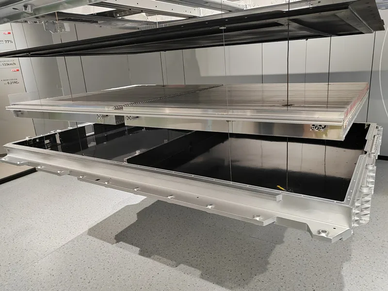
Aluminum busbars are increasingly used in electric vehicle (EV) battery packs as lightweight electrical conductors for connecting battery cells, modules, high-voltage circuits, and power distribution components. Compared with conventional cable-based connections, busbars provide a more compact and rigid current path while allowing the conductor geometry to be precisely adapted to the limited space inside a battery pack.
The application of aluminum busbars is not limited to one specific battery component. Depending on the battery architecture, current level, connection method, available space, and thermal management system, aluminum busbars can be used in cell-level interconnections, module connections, high-voltage PACK circuits, and battery distribution assemblies.
For battery manufacturers and component designers, the key question is therefore not simply whether aluminum can conduct the required current. The more important question is how the aluminum busbar should be designed, processed, and selected for its specific position within the battery system.
Where Are Aluminum Busbars Used in EV Battery Packs?
An EV battery pack contains multiple electrical connection levels. Current flows from individual cells through cell and module interconnections before reaching the pack-level high-voltage circuit and external electrical connections.
This creates several different busbar applications, each with its own requirements.
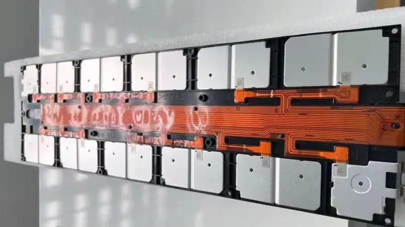
CCS and Cell-Level Aluminum Busbars
At the cell level, busbars are used to connect individual battery cells or groups of cells. In many battery architectures, these conductors are integrated into a Cell Contact System (CCS), together with voltage-sensing circuits, insulating structures, and other components.
Cell-level aluminum busbars are generally designed around a compact and highly integrated structure. Instead of simply providing a large current path, they may need to follow the arrangement of individual cells and accommodate multiple connection points within a limited space.
Typical design considerations include:
Compact dimensions and complex routing
Multiple current branches
Cell terminal or tab connection
Laser or ultrasonic welding
Voltage-sensing integration
Insulation and electrical isolation
Burr and edge control
Flatness and dimensional consistency
For this type of application, the busbar geometry can be just as important as the material itself. The thickness, width, bend position, welding area, and clearance from adjacent components all have to work together.
The selection between aluminum and copper also depends on the battery cell format and connection design. Research on EV battery interconnections shows that both Al and Cu busbars are used, with material and thickness selected according to current capacity, thermal management, joining requirements, weight, and electrical efficiency.
Module-Level Aluminum Busbars
Between the cell level and the complete battery pack is the module level. Depending on the battery architecture, busbars can be used to collect current from multiple cells and establish electrical connections between battery modules.
Compared with cell-level CCS conductors, module busbars generally have greater current-carrying requirements. At the same time, their shape must still fit within the module housing and maintain sufficient clearance from surrounding structural and electrical components.
This makes module busbars a balance between:
electrical capacity + mechanical strength + thermal performance + packaging space.
The required cross-section is not determined by current alone. Continuous current, peak current, duty cycle, conductor length, cooling conditions, allowable temperature rise, and the surrounding battery structure all influence the final busbar dimensions.
PACK High-Voltage Aluminum Busbars
At the pack level, busbars form part of the main high-voltage electrical circuit. They can connect battery modules to one another and connect the battery assembly to major high-voltage components.
These busbars typically face substantially higher current and voltage requirements than many cell-level conductors. Consequently, the design places greater emphasis on conductor cross-section, temperature rise, insulation, mechanical stability, and connection reliability.
PACK high-voltage aluminum busbars may use:
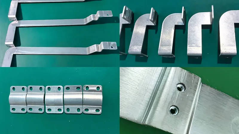
Flat or formed rectangular sections
Bent or offset sections for space optimization
Bolted connection areas
Insulating supports
Heat-shrink insulation or protective coatings
Copper-aluminum transition structures where required
The connection method also changes the design. A bolted high-current connection needs sufficient contact area, controlled clamping force, appropriate surface treatment, and long-term mechanical stability. In contrast, a welded cell-level connection places greater emphasis on weld geometry, weld penetration, joint resistance, and local heat input.
This is why an aluminum busbar for a PACK high-voltage circuit should not simply be treated as a larger version of a CCS busbar. The electrical and mechanical requirements are different.
BDU, PDU and High-Voltage Terminal Connections
Battery Distribution Units (BDUs) and Power Distribution Units (PDUs) contain important high-voltage components such as contactors, fuses, current sensors, pre-charge circuits, and external electrical terminals.
Busbars in these areas provide relatively short but important current paths between high-voltage components. Because the available installation space can be limited, the busbar geometry often needs to be optimized around the components rather than designed as a simple straight conductor.
At this stage, electrical performance and mechanical integration become closely connected. A busbar may need to include holes, bends, offsets, terminal sections, or different connection surfaces while maintaining sufficient cross-sectional area and insulation clearance.
Therefore, aluminum busbars used in BDU/PDU applications should be evaluated according to the actual current, connection interface, available space, thermal conditions, and required mechanical strength rather than assigned a specific alloy solely because of the application name.
Key Aluminum Busbar Design Requirements for EV Battery Packs
Although CCS, module, PACK, and BDU/PDU busbars have different structures, their design ultimately needs to solve several common engineering problems.
Current-Carrying Capacity
The first consideration is the current that the busbar must carry.
However, continuous current alone is not enough to determine the required dimensions. EV battery loads vary during acceleration, regenerative braking, charging, and fast-charging operation. The busbar therefore needs to account for both continuous and peak current as well as peak duration and duty cycle.
A larger cross-sectional area generally reduces electrical resistance and heat generation. Since resistive losses increase with the square of current, even a relatively small increase in current can have a significant effect on heat generation.
Cross-Section and Geometry
For aluminum busbars, conductor width and thickness must be balanced against the available installation space.
Increasing the cross-section can reduce resistance and temperature rise, but the resulting busbar may become too large for the battery architecture. Engineers therefore need to consider the complete current path rather than simply increasing thickness.
The geometry may include:
Straight sections
Bends
Slots
Mounting holes
Weld tabs
Offset sections
Terminal pads
Transition sections
This is particularly important in EV battery packs because the available space is highly constrained.
Temperature Rise and Thermal Management
Temperature rise is one of the most important considerations in battery busbar design.
Electrical resistance generates heat as current passes through the conductor. The actual temperature rise depends not only on material resistivity and cross-sectional area, but also on conductor length, surface area, surrounding temperature, airflow, contact resistance, and the battery pack's cooling system.
Fast charging and high-power discharge make thermal management increasingly important. The interaction between busbar material, cross-sectional area, contact resistance, weld design, and thermal behavior can directly affect the reliability of the battery electrical system.
For this reason, a busbar that performs adequately under a low-current condition may require a different geometry when used in a high-current or fast-charging battery system.
Connection Method
The connection method has a direct influence on busbar design.
Depending on the battery architecture, aluminum busbars may be connected by:
Laser welding
Ultrasonic welding
Mechanical fastening
Bolted connections
Riveting
Aluminum-copper transition joints
Other specialized joining processes
For welded connections, the weld area, penetration, joint resistance, heat input, and surrounding material must be considered. For bolted connections, contact pressure, contact area, surface condition, vibration, and long-term mechanical stability become more important.
Aluminum-to-copper connections require additional attention because dissimilar-metal joining can produce intermetallic compounds and electrical resistance changes if the joint is not properly designed.
Insulation and Electrical Clearance
In a high-voltage battery pack, the busbar is not only an electrical conductor but also a component that must coexist safely with the surrounding structure.
The design may need to accommodate:
Insulating supports
Protective coatings
Heat-shrink materials
Creepage distance
Electrical clearance
Protection against accidental contact
Isolation from the battery housing
The shape of an aluminum busbar must therefore be designed together with its insulation system rather than considered separately.
Mechanical Reliability
EV battery packs experience vibration, mechanical shock, thermal cycling, and repeated expansion and contraction during service.
A busbar must maintain its electrical connection throughout these conditions. For bolted connections, long-term clamping force and joint stability are particularly important. For welded connections, weld strength and fatigue resistance need to be considered.
This is another reason why the best busbar design is not necessarily the smallest or lightest one. The conductor must provide the required electrical performance while maintaining mechanical reliability over the expected service life.
Aluminum Alloy Selection for EV Battery Busbars
There is no single aluminum alloy that is universally suitable for every EV battery busbar.
The appropriate alloy depends on the required electrical conductivity, strength, formability, cross-sectional geometry, joining process, and manufacturing method.
1xxx Series Aluminum for High Electrical Conductivity
Commercially pure aluminum grades in the 1xxx series are attractive for electrical conductor applications because of their relatively high electrical conductivity and good formability.
Depending on the specific design and required properties, grades such as 1050, 1060, and 1070 may be considered for electrical busbar applications.
These alloys can be useful when electrical conductivity and forming characteristics are more important than high mechanical strength.
For cell-level and other compact conductors, the material selection should still be evaluated together with thickness, weldability, current level, and the requirements of the battery terminal.
6101 Aluminum for Conductivity and Mechanical Performance
6101 aluminum is another important alloy to consider for electrical conductor applications where a combination of electrical conductivity and mechanical strength is required.
Compared with commercially pure aluminum, an alloy such as 6101 can provide a different balance between conductivity and mechanical properties, which can be useful when the busbar needs to maintain its shape or withstand mechanical loads.
6101 aluminum busbars are commonly used for high-voltage PACK busbars, particularly where a balance of electrical conductivity and mechanical strength is required. The specific grade and temper, such as 6101-T6 or 6101-T65, should be selected according to the actual electrical and mechanical requirements of the component.
Alloy Selection Should Follow the Busbar Design
The correct question is not simply:
“Which aluminum alloy is the best for battery busbars?”
A better question is:
“Which alloy provides the required balance of conductivity, strength, formability, joining performance, and weight for this specific busbar design?”
For example, a thin stamped conductor may prioritize formability and conductivity, while a larger formed or extruded conductor may require greater mechanical stability.
The same battery pack may therefore contain aluminum busbars made with different material specifications depending on their electrical and structural functions.
Aluminum vs. Copper in EV Battery Pack Applications
Aluminum and copper are both established conductor materials for EV battery interconnections, but their roles are not identical.
Copper provides higher electrical conductivity and allows a smaller conductor cross-section for a given electrical requirement. This can be valuable where installation space is extremely limited or where very high current must be carried through a compact connection.
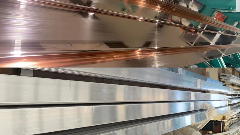
Common copper materials used as electrical busbars: Cu-ETP flat bar/C11000 copper bar and other high-conductivity copper grades.
Aluminum, on the other hand, has a major advantage in weight. Its density is only about one-third that of copper, so an aluminum conductor can provide significant mass savings when the battery architecture has enough space to accommodate the required cross-section.
This difference is particularly relevant to EV battery design, where reducing battery-pack mass can contribute to overall vehicle efficiency. The choice between aluminum and copper therefore involves conductivity, weight, thermal behavior, joining, and packaging rather than simply which material has higher electrical conductivity.
In practical EV battery systems, aluminum is particularly attractive for lightweight cell and module interconnections and other applications where a larger conductor cross-section can be accommodated. Depending on the battery architecture, electrical-grade aluminum such as 1xxx-series alloys or other suitable aluminum alloys can be considered.
Copper remains important in compact, high-current connections where electrical conductivity and limited installation space are dominant considerations. C11000 / Cu-ETP and similar high-conductivity copper materials are commonly considered for these applications.
Some battery systems can also use both aluminum and copper within the same electrical architecture. Instead of replacing one material everywhere, engineers can use aluminum where weight and cost reduction are important and copper where compact high-current conduction is more critical. Hybrid aluminum-copper busbar structures are also being investigated for EV battery applications.
Therefore, aluminum should not be viewed simply as a lower-conductivity substitute for copper. In an EV battery pack, aluminum provides a different engineering balance: lower density, lightweight construction, good conductivity, and flexible forming options. When the battery architecture provides sufficient space for the required cross-section, these advantages can make aluminum busbars an effective solution for reducing conductor weight while maintaining the required electrical performance.
Why Aluminum Busbars Are Important for the Next Generation of EV Batteries
As EV battery systems move toward higher energy density, faster charging, higher pack voltages, and more compact integration, busbars are becoming increasingly important to the overall electrical and thermal performance of the battery pack.
An aluminum busbar is therefore not simply a piece of metal connecting two terminals. Its width, thickness, alloy, geometry, connection method, insulation, and thermal environment all influence the reliability of the complete battery system.
From cell-level CCS connections to module interconnections, PACK high-voltage circuits, and BDU/PDU assemblies, aluminum busbars can be engineered in different forms according to the electrical and structural requirements of each application.
For manufacturers and battery-system integrators, the material should be selected together with the complete busbar design rather than in isolation. The right combination of aluminum alloy, cross-section, geometry, joining method, surface condition, and thermal management can help achieve the required current capacity while reducing weight and maintaining long-term reliability.
For customized EV battery busbars, material grade, temper, thickness, width, length, hole configuration, bending requirements, surface treatment, and joining method should be specified according to the actual battery architecture and electrical load.