Copper vs. Aluminum Flexible Busbar Connections
1. What Is a Flexible Busbar Connection?
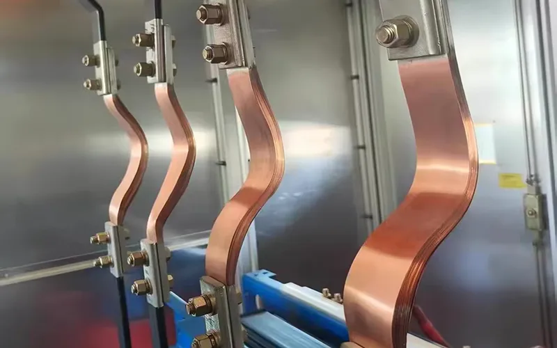
A flexible busbar connection is a conductive component used in electrical equipment and power distribution systems. It is typically made by stacking and welding multiple layers of thin metal foil, with solid metal terminals or busbars attached at both ends. This construction combines electrical conductivity with mechanical flexibility.
Unlike conventional rigid busbar connections, flexible busbar connections can accommodate vibration, displacement, and thermal expansion during equipment operation. This helps reduce mechanical stress on connection points. Their flexible design also makes them suitable for installations with limited internal space or irregular mounting positions.
Based on the conductive materials used, flexible busbar connections generally fall into three categories: copper flexible busbar connections, aluminum flexible busbar connections, and copper-aluminum flexible busbar connections.
A copper flexible busbar typically uses multiple layers of copper foil as its flexible conductive section, with copper busbars or terminals at both ends. An aluminum flexible busbar uses aluminum foil for the flexible section and aluminum busbars or terminals for the end connections. Copper-aluminum flexible busbar connections combine the characteristics of both metals through different foil and terminal configurations.
2. Applications of Copper and Aluminum Flexible Busbar Connections
Copper and aluminum flexible busbar connections serve essentially the same purpose: they transmit electrical current while providing flexibility at the connection points.
During the operation of electrical equipment, vibration, thermal expansion and contraction, and changes in operating conditions can all place mechanical stress on electrical connections. Over time, these stresses may cause fatigue in rigid connections, loosen contact points, or reduce connection reliability.
The layered foil structure of a flexible busbar allows it to bend and accommodate a certain amount of displacement. This reduces the direct transfer of external mechanical stress to the terminals and helps maintain stable connection performance.
Common applications include:
2.1 Power Transformers and Switchgear
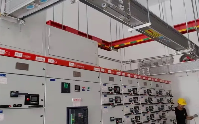
Transformers, switchgear cabinets, and power distribution equipment carry continuous electrical loads and may also be exposed to electromagnetic forces, mechanical vibration, and temperature fluctuations.
Flexible busbar connections can be used between transformer windings, busbars, and other conductive components. Their flexibility helps accommodate minor displacement and vibration during equipment operation.
2.2 Power Distribution Systems and Busbar Connections
In low-voltage distribution cabinets, busway systems, and other power distribution installations, flexible busbar connections are commonly used between busbars or between busbars and equipment terminals.
Their flexible structure accommodates installation tolerances and reduces the mechanical load that rigid connections may place on equipment terminals.
2.3 Renewable Energy and Energy Storage Equipment
Energy storage systems, photovoltaic inverters, and other renewable energy equipment often have high current transmission requirements. Flexible busbar connections can be used between battery modules, collector busbars, inverters, and other electrical components.
2.4 Electric Vehicles and Industrial Equipment
In electric vehicle battery systems, motors, and industrial power supply equipment, flexible busbar connections can accommodate vibration and thermal deformation during operation, helping reduce mechanical stress at connection points.
Overall, copper and aluminum flexible busbar connections have largely overlapping application areas. Their main differences come from the properties of the conductive materials and how these properties affect structural design, manufacturing processes, and cost.
3. Material Property Comparison: Copper vs. Aluminum
Copper and aluminum are both widely used electrical conductors, but they differ significantly in electrical conductivity, density, thermal conductivity, and mechanical properties. These differences directly affect the cross-sectional area, weight, temperature rise, and structural design of flexible busbar connections.
3.1 Electrical Conductivity and Resistivity
Copper has higher electrical conductivity than aluminum. With the same cross-sectional area and length, a copper conductor has lower electrical resistance. It can therefore carry more current or reduce resistive losses under the same current load.
Aluminum has approximately 61% of the electrical conductivity of standard annealed copper. Under theoretical DC conditions at 20°C, an aluminum conductor requires approximately 1.6 times the cross-sectional area of a copper conductor to achieve the same resistance.
In practical engineering applications, however, additional design margins are necessary. Heat dissipation, AC skin effect, and allowable temperature rise must also be considered. The 1.6 ratio should not be applied directly as a universal sizing factor.
When designing copper or aluminum flexible busbar connections, the foil thickness, number of layers, and total cross-sectional area should therefore be determined according to the rated current, allowable temperature rise, available installation space, and connection structure.
3.2 Density and Weight
The density of copper is approximately 8.96 g/cm³, while that of aluminum is approximately 2.70 g/cm³.
Aluminum has only about 30% of the density of copper. As a result, an aluminum flexible busbar is significantly lighter than a copper one of the same volume.
This makes aluminum a practical option for applications where overall equipment weight needs to be controlled. In large power distribution equipment and renewable energy systems, using aluminum conductors can also help reduce the total weight of conductive components.
3.3 Thermal Conductivity
Both copper and aluminum have good thermal conductivity, but copper conducts heat more effectively.
Copper can transfer heat away from connection points more quickly. Aluminum has a lower thermal conductivity, so when designing aluminum flexible busbar connections under comparable current and structural conditions, greater attention should be paid to conductor cross-sectional area, heat dissipation, and temperature rise at the connection points.
3.4 Melting Point and Coefficient of Thermal Expansion
Copper has a melting point of approximately 1,085°C, while aluminum melts at approximately 660°C.
The lower melting point of aluminum affects its welding processes and processing parameters. During the welding of multiple foil layers, heat input must be carefully controlled to prevent localized overheating, material deformation, or welding defects.
The linear coefficient of thermal expansion is approximately 16.5 × 10⁻⁶/K for copper and 23 × 10⁻⁶/K for aluminum. Aluminum therefore undergoes greater dimensional changes when temperatures fluctuate. This difference should be taken into account when designing flexible busbar structures.
3.5 Mechanical Properties and Flexibility
The mechanical properties of copper and aluminum depend on the alloy grade, material temper, thickness, and processing method.
Copper foil generally offers good ductility and processing stability, making it suitable for layered flexible conductive structures. Aluminum foil is lighter and also has good formability, although its mechanical strength and surface oxidation characteristics differ from those of copper.
The flexibility of a busbar connection depends not only on the metal itself but also on several structural factors, including individual foil thickness, number of foil layers, effective flexible length, minimum allowable bending radius, and the design of the welded areas.
Stacking multiple layers of thin foil makes it possible to maintain the required conductive cross-sectional area while allowing the connection to bend.
4. Manufacturing Processes of Copper and Aluminum Flexible Busbar Connections
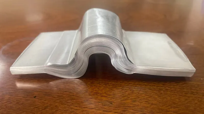
The basic manufacturing processes for copper and aluminum flexible busbar connections are similar. They generally include foil preparation, stacking, welding the foil layers together, joining the foil assembly to solid connection terminals, and subsequent finishing and surface treatment.
The main differences in processing copper and aluminum come from their distinct physical properties, surface conditions, and welding characteristics.
4.1 Foil Preparation and Stacking
Copper or aluminum foil is prepared according to the specified thickness and width required by the product design.
Foil thickness, width, and the number of layers determine the total cross-sectional area of the flexible section, directly affecting its current-carrying capacity and bending performance.
The foil is then cut, arranged, and stacked to the required dimensions. During this process, the foil layers should remain flat and properly aligned, with local gaps and misalignment kept to a minimum.
4.2 Welding Between Foil Layers
After stacking, the designated areas of the foil layers are welded together to form a stable conductive connection.
Ultrasonic metal welding is a mainstream process used in mass production. It is a pressure-welding process that produces a solid-state bond between metal layers.
Diffusion welding is a specialized process mainly used in laboratory settings or for very small production batches with specific operating requirements. It is not a conventional mass-production method.
Copper and aluminum have different welding characteristics. Copper has high thermal conductivity, so heat input must be properly controlled during welding. Aluminum readily forms an oxide film on its surface, making surface preparation and welding parameters particularly important. During ultrasonic welding, mechanical vibration helps break the aluminum oxide film, allowing reliable metal-to-metal bonding.
4.3 Welding the Foil Assembly to Solid Connection Ends
After the foil layers have been welded together, the foil assembly is joined to solid metal connection materials at both ends.
A copper flexible busbar typically consists of a copper foil assembly connected to copper busbars or copper terminals. An aluminum flexible busbar uses an aluminum foil assembly connected to aluminum busbars or aluminum terminals.
The welded joints must provide sufficient bonding strength and low contact resistance. The dimensions and flatness of the welding areas, together with the overall connection quality, affect the electrical performance of the finished product.
4.4 Subsequent Processing and Surface Treatment
After welding, the flexible busbar connection may undergo trimming, punching, bending, and dimensional finishing according to the design requirements.
Some products may also require tin plating, nickel plating, or other surface treatments. It is important to note that plating should only be applied to the solid terminal areas at both ends. The flexible foil section in the middle must not be tin-plated or nickel-plated. At high temperatures, the coating may melt and cause adjacent foil layers to stick together, resulting in a permanent loss of flexibility.
Surface treatment requirements also differ between copper and aluminum. Aluminum naturally forms an oxide film, while copper gradually oxidizes when exposed to air. The appropriate surface protection method should therefore be selected according to the material, operating environment, and connection method.
5. Electrical Performance and Connection Reliability
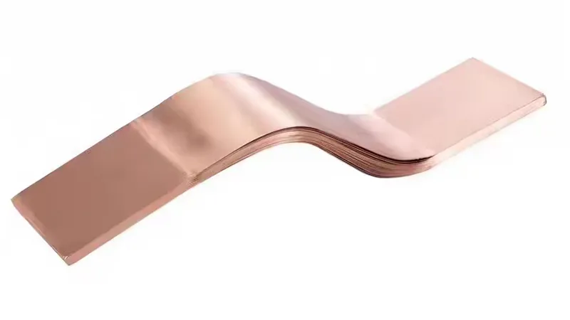
The primary function of a flexible busbar connection is to transmit electrical current. Electrical conductivity, temperature rise, and contact resistance are therefore key indicators when evaluating product quality and connection reliability.
The basic electrical analysis in this chapter is based on DC operating conditions. Under high-current AC conditions, skin effect and proximity effect must also be considered. These effects reduce the effective current-carrying capacity of multilayer foil flexible busbar connections, so appropriate AC derating is necessary.
In addition, heat dissipation from a multilayer foil stack is generally less effective than that of a solid busbar. Current derating should therefore also be considered when selecting the overall flexible busbar connection.
5.1 Current-Carrying Capacity
The current-carrying capacity of a flexible busbar connection depends on several factors, including the conductive material, total cross-sectional area, effective length, heat dissipation conditions, and ambient operating temperature.
Copper has higher electrical conductivity than aluminum and therefore offers lower resistance at the same cross-sectional area. To achieve a similar resistance, an aluminum conductor generally requires a larger cross-sectional area.
For multilayer foil structures, foil thickness, the number of layers, and the effective conductive area of the welded sections also influence current-carrying capacity.
5.2 Temperature Rise and Resistive Losses
When current flows through a conductor, electrical resistance generates heat. The power loss can be calculated using the following formula:
P = I²R
Where:
P = Resistive power loss (W)
I = Current flowing through the conductor (A)
R = Electrical resistance of the conductor (Ω)
At the same current, a conductor with higher resistance generates more heat. Copper and aluminum flexible busbar connections should therefore be designed according to their respective resistance characteristics, cross-sectional areas, and heat dissipation conditions.
Weld quality at the terminal areas is also important. Incomplete bonding or insufficient effective contact area can increase local resistance and lead to hot spots.
5.3 Surface Oxidation and Contact Resistance
Both copper and aluminum form oxide layers when exposed to air, but their surface characteristics differ.
Copper gradually develops surface oxides. Prolonged exposure to humid or corrosive environments can further change its surface condition.
Aluminum readily forms a dense aluminum oxide film. Although this film protects the underlying metal, it has poor electrical conductivity. If the oxide film is not properly addressed at the connection interface, contact resistance may increase.
In industrial production, ultrasonic welding uses mechanical vibration to break the oxide film on aluminum surfaces and establish a conductive bond.
Welding areas and actual electrical contact surfaces should be treated according to the properties of the material to ensure stable electrical connections.
5.4 Welding Quality and Connection Stability
A flexible busbar connection contains two main types of welded areas: the joints between individual foil layers and the joints connecting the foil assembly to the solid terminals.
Both types of joints must provide sufficient bonding strength and stable electrical conductivity.
The bonding quality between foil layers affects the overall conductivity and mechanical stability of the flexible section. Meanwhile, the connection between the foil assembly and solid terminals directly affects interface resistance and the reliability of the finished product.
The welding process, material surface condition, and dimensions of the welded areas must therefore be effectively controlled.
6. Cost Comparison: Copper Flexible Busbar vs. Aluminum Flexible Busbar
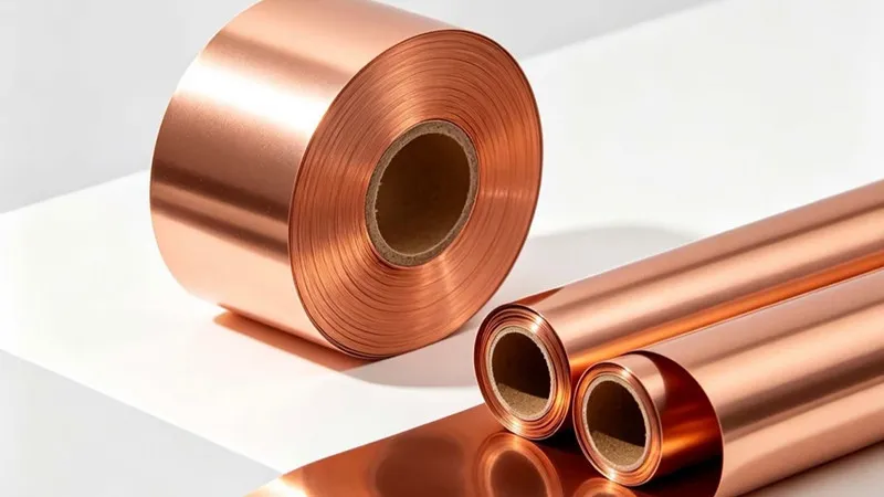
Differences in material prices, density, and processing characteristics result in different raw material and overall manufacturing costs for copper and aluminum flexible busbar connections.
6.1 Raw Material Cost
Copper generally has a higher price per unit weight than aluminum. In addition, copper has a density approximately 3.3 times that of aluminum.
For the same volume, copper weighs significantly more, which generally results in a higher raw material cost.
Aluminum has a much lower density. In applications requiring large quantities of conductive material, its lower weight can help reduce material costs.
6.2 Material Quantity for Equivalent Conductivity
The electrical conductivity of copper is approximately 1.6 times that of aluminum.
To achieve the same resistance, an aluminum conductor generally requires a larger cross-sectional area. Based on commonly used conductivity data, the cross-sectional area of aluminum is approximately 1.6 times that of copper for an equivalent resistance.
Despite the larger cross-sectional area, an aluminum conductor may still weigh less than a copper conductor under equivalent resistance requirements because of aluminum's much lower density.
Therefore, cost comparisons should consider the unit price of the material, required cross-sectional area, number of foil layers, and overall product structure rather than relying solely on the price per kilogram.
6.3 Processing Cost
Processing costs depend on factors such as material thickness, welding method, equipment, and product quality requirements.
Copper has higher thermal conductivity, so heat input must be carefully controlled during welding. Aluminum requires attention to oxide film removal and process protection, which also affects manufacturing requirements.
For multilayer foil structures, foil thickness, number of layers, welding area, and subsequent machining or finishing requirements all influence production costs.
As a result, the final cost of a flexible busbar connection depends not only on the price of the metal itself but also on the product design and manufacturing process.
7. Service Life, Mechanical Fatigue and Operating Environment
The flexible structure of a busbar connection allows it to accommodate a certain degree of vibration and displacement. However, its service life still depends on the material, structural design, and actual operating conditions.
7.1 Mechanical Fatigue
In operating environments involving long-term vibration or repeated bending, the foil layers may be subjected to cyclic mechanical stress.
The thickness of each foil layer, length of the flexible section, bending radius, and mounting method all affect fatigue life.
A properly designed structure can reduce localized stress concentrations and lower the risk of fatigue damage to the foil layers during long-term operation.
7.2 Effects of Thermal Cycling
Electrical equipment experiences load variations and temperature fluctuations during operation. As conductors expand when heated and contract when cooled, the connection areas are subjected to repeated thermomechanical stress.
Aluminum has a higher coefficient of thermal expansion than copper. Therefore, in applications involving significant temperature variations, the thermal expansion characteristics of the selected material should be taken into account during structural design.
7.3 Operating Environment
Temperature, humidity, dust, and corrosive substances can all affect the long-term performance of flexible busbar connections.
In humid or corrosive environments, attention should be paid to surface oxidation and corrosion.
For copper-aluminum structures, significant galvanic corrosion occurs only when an electrolyte, such as moisture or salt spray, creates a conductive path between the two metals. In dry environments, galvanic corrosion caused by direct copper-aluminum contact is generally very limited.
Therefore, potential corrosion at the interface between the two metals should be considered when designing copper-aluminum flexible busbar connections.
8. Surface Treatment and Protection
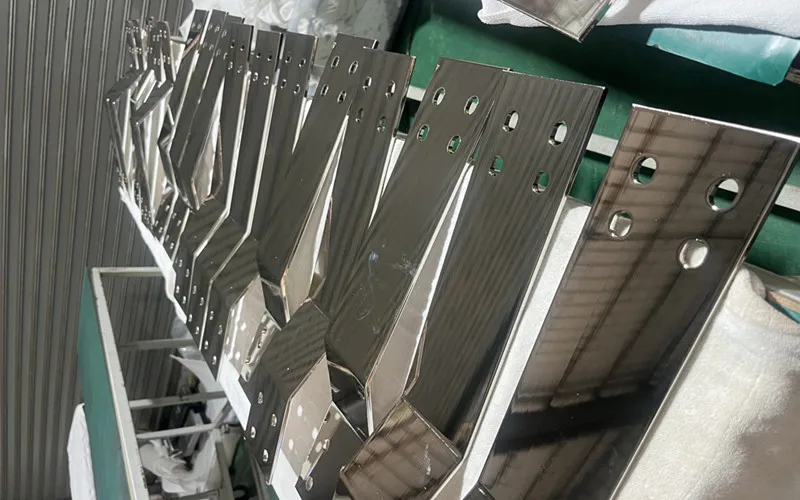
Surface treatment can improve the condition of connection interfaces and help flexible busbar connections adapt to specific operating environments.
Important: Plating should only be applied to the solid terminals at both ends. Electroplating must not be applied to the flexible foil section.
Common surface treatment methods include:
8.1 Tin Plating
Tin plating is a common surface treatment for the solid terminals of copper flexible busbar connections. The tin coating helps improve the surface condition of copper connection components, reduces the effects of further copper oxidation, and helps provide a stable electrical contact interface.
Additional engineering consideration: Aluminum components are difficult to tin-plate directly. Aluminum terminals generally do not use conventional tin plating. Instead, conductive paste or copper-aluminum transition connectors are commonly used.
8.2 Nickel Plating
Nickel plating can improve surface hardness and corrosion resistance. It is suitable for electrical connection components with specific environmental requirements and should likewise be applied only to solid terminal areas.
8.3 Aluminum Surface Treatment
Aluminum readily forms an oxide film on its surface. In practical electrical connections, appropriate surface treatment should be selected according to the connection structure and operating environment to ensure good electrical conductivity at the contact interface.
Common methods include:
Breaking the oxide film during welding.
Mechanical polishing or abrasion of contact surfaces.
Applying conductive paste for protection.
Direct tin electroplating is generally not used for aluminum components.
8.4 Insulation and Protection
For flexible busbar connections that must be electrically isolated from other conductive components, insulating sleeves, insulating coatings, or other protective structures can be added according to equipment requirements.
Engineering note: Insulating sleeves and coatings must be compatible with the maximum allowable temperature rise of the conductor. Insulation materials should be selected according to the required temperature rating and actual operating temperature.
The specific protection method should be determined based on operating voltage, temperature, environmental conditions, and installation requirements.
9. Copper-Aluminum Flexible Busbar Connections
Copper-aluminum flexible busbar connections combine the characteristics of copper and aluminum. They are commonly used in electrical systems where copper conductors need to be connected to aluminum conductors.
Their structural designs are not limited to one configuration. Common options include an aluminum foil flexible section combined with copper connection terminals, or the use of copper-aluminum clad transition components to connect the two metals.
9.1 Common Structures
One common design uses aluminum foil as the flexible conductive section, with copper busbars or copper terminals at the connection ends. This allows the assembly to connect to copper electrical components.
Another design uses copper foil as the flexible conductive section, with aluminum connection terminals for integration into an aluminum conductor system.
For direct connections between copper and aluminum, copper-aluminum clad transition materials can also be used to reduce interface problems associated with direct contact between the two metals.
9.2 Technical Challenges in Copper-Aluminum Connections
Copper and aluminum have different physical properties, melting points, and surface oxidation characteristics, which can create challenges during direct welding.
The aluminum oxide film on the surface has a much higher melting point than the aluminum base metal, making it difficult to form a sound welding interface. In addition, under fusion-welding conditions, copper and aluminum can readily form thick, brittle intermetallic compound layers, reducing joint strength and electrical stability.
Ultrasonic solid-state pressure welding can help suppress excessive growth of brittle intermetallic compound layers.
Furthermore, electrochemical corrosion between directly connected copper and aluminum occurs only when an electrolyte is present, such as in humid or salt-spray environments. Therefore, copper-aluminum flexible busbar connections require properly designed transition structures and appropriate protection at the connection interface.
9.3 Applications of Copper-Aluminum Flexible Busbar Connections
Copper-aluminum flexible busbar connections are commonly used for transition connections between copper busbars and aluminum conductors, as well as in certain power equipment, renewable energy systems, and power distribution installations.
The main design priorities are to ensure connection quality at the copper-aluminum interface while meeting the equipment's requirements for current-carrying capacity, mechanical flexibility, and service life.
10. Quality Inspection of Copper and Aluminum Flexible Busbar Connections
Quality inspection of flexible busbar connections mainly focuses on dimensions, electrical conductivity, welding quality, and mechanical properties.
10.1 Dimensional Inspection
Check the overall length, width, thickness, number of foil layers, terminal dimensions, and mounting hole positions to ensure that the product meets the design requirements.
10.2 Electrical Resistance Testing
Measuring the DC resistance of a flexible busbar connection helps evaluate its electrical conductivity and connection quality.
Resistance measurements should be analyzed in conjunction with product dimensions, material properties, and test conditions. For products operating under high-current AC conditions, AC resistance testing is also recommended where testing facilities and conditions permit.
10.3 Temperature Rise Testing
Conduct a current-carrying test under specified current conditions and record the temperature changes in the flexible busbar connection and its terminal areas. The results are then evaluated to determine whether the temperature rise meets the design requirements.
For AC operating conditions, the test should be conducted using an AC power supply.
10.4 Welding Quality Inspection
Inspect the welded areas between the foil layers and the joints between the foil assembly and solid terminals. Particular attention should be paid to weld integrity, bonding strength, and any visible defects.
10.5 Mechanical Testing
Depending on the product application, tensile, bending, or vibration-related tests can be performed to evaluate the stability of the flexible busbar connection under mechanical loads and long-term operating conditions.
Bending fatigue tests must be conducted strictly according to the minimum bending radius specified for the product.
11. The Roles of Copper Foil, Aluminum Foil, Copper Busbars and Aluminum Busbars in Flexible Busbar Manufacturing
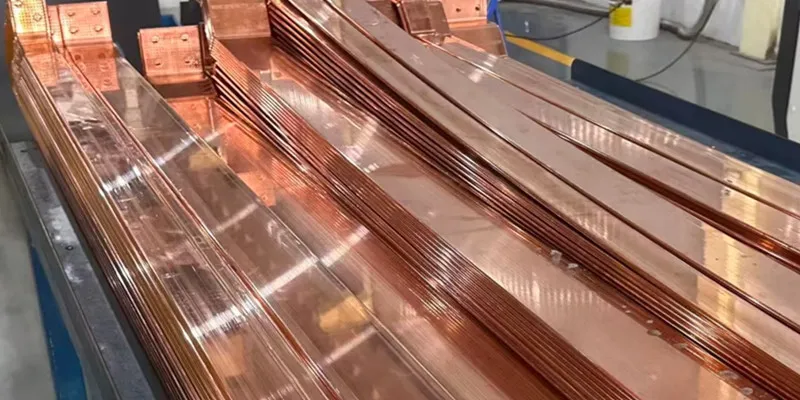
A flexible busbar connection generally consists of flexible foil material and solid connection materials at both ends. The foil forms the flexible conductive section, while the solid materials provide connections to equipment terminals or busbar systems.
The selection of copper foil, aluminum foil, copper busbars, and aluminum busbars affects the electrical conductivity, welding performance, mechanical strength, and overall structure of the finished connection.
11.1 Common Materials for Copper Flexible Busbar Connections
Copper flexible busbar connections generally use multiple layers of copper foil to form the flexible conductive section, with copper busbars or copper terminals connected at both ends.
Common copper foil and busbar materials include:
T2 / C11000 / Cu-ETP: Common electrical-grade copper with good electrical conductivity and processing properties. It is a widely used material option for copper flexible busbar connections.
TU2 / C10200 / Cu-OF: Oxygen-free copper with high purity and good electrical conductivity. It is suitable for applications with specific requirements for material purity and electrical performance.
T2, C11000, and Cu-ETP are commonly referenced as corresponding materials within different designation systems. Similarly, TU2, C10200, and Cu-OF are often used as reference designations for oxygen-free copper. The exact grade should be confirmed according to the applicable standard and chemical composition requirements.
In copper flexible busbar connections, copper foil is mainly used to form the multilayer flexible conductive structure, while copper busbars provide the rigid connection sections at both ends.
11.2 Common Materials for Aluminum Flexible Busbar Connections
Aluminum flexible busbar connections generally use multiple layers of aluminum foil for the flexible section, with aluminum busbars or aluminum terminals at both ends.
Common materials include:
1050: Commercially pure aluminum with good ductility and processing properties.
1060: Common high-purity aluminum with good electrical conductivity and ductility. It is widely used for aluminum foil and aluminum busbars.
1070: Aluminum with a relatively high aluminum content and good electrical conductivity, suitable for applications requiring good conductive performance.
1350: Electrical-grade aluminum commonly used for electrical conductors and conductive connection components.
6101: A heat-treatable Al-Mg-Si alloy that combines electrical conductivity with mechanical strength. It is commonly used for electrical busbars and other conductive structural components, but is generally not used to manufacture aluminum foil.
Among these materials, 1050, 1060, 1070, and 1350 can be used for aluminum foil or aluminum busbars. Grade 6101 is mainly used for aluminum busbars and other structural components that require a balance of electrical conductivity and mechanical strength.
The thickness, number of layers, and temper of aluminum foil affect the processing performance of the flexible section. Aluminum busbars should be selected according to the mechanical strength, electrical requirements, and welding process required at the connection ends.
11.3 Common Materials for Copper-Aluminum Flexible Busbar Connections
Copper-aluminum flexible busbar connections must be designed with consideration for the materials used in both the flexible section and the connection terminals.
Common material combinations include:
Aluminum foil + copper busbars or copper terminals: The flexible section uses 1060 or 1350 aluminum foil, while the connection ends use T2 or TU2 copper materials.
Copper foil + aluminum busbars or aluminum terminals: The flexible section uses T2 or TU2 copper foil, while the connection ends use aluminum materials suitable for the selected joining process.
Copper-aluminum clad transition structure: Copper-aluminum clad transition components are used between copper and aluminum to provide a connection between the two metals.
The key to designing copper-aluminum flexible busbar connections is the interface between the dissimilar metals. Welding characteristics, interface resistance, differences in thermal expansion, and the risk of electrochemical corrosion in electrolyte-containing environments must all be considered.
11.4 Summary of Common Material Grades
Flexible Busbar Type | Flexible Foil Material | Solid Connection Material |
|---|---|---|
Copper flexible busbar | T2, TU2, C11000, C10200 | T2, TU2, C11000, C10200 |
Aluminum flexible busbar | 1050, 1060, 1070, 1350 | 1050, 1060, 1070, 1350, 6101 |
Copper-aluminum flexible busbar | 1060 or 1350 aluminum foil, or T2 or TU2 copper foil | T2 or TU2 copper terminals, aluminum terminals, or copper-aluminum clad transition components |
The materials listed above represent common options. The specific grade and temper should be determined according to the product structure, electrical requirements, welding process, and applicable standards.
Grade equivalencies across different national and international standards should also be verified against the actual chemical composition and relevant standard requirements.
12. Conclusion
Copper and aluminum flexible busbar connections have similar basic structures and functions. Both use multiple layers of metal foil to form a flexible conductive section, which is joined to solid connection materials at both ends to provide electrical conductivity and flexibility in electrical systems.
Their main differences come from the material properties of copper and aluminum. Copper offers higher electrical and thermal conductivity, while aluminum has the advantages of lower density and lighter weight. These differences further affect the required cross-sectional area, structural design, welding process, temperature rise, and material cost of flexible busbar connections.